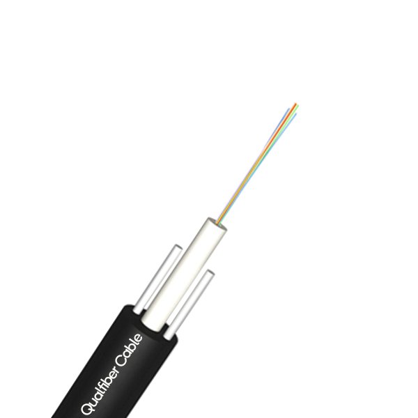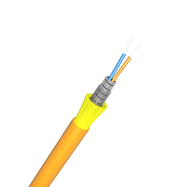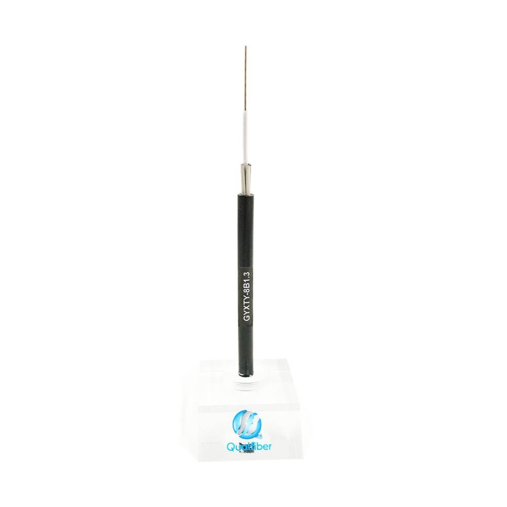
The submarine optical cable is laid on the seabed with a wire bundle wrapped in an insulating sheath. The sea water can prevent the interference of external optical and magnetic waves, so the signal-to-noise ratio of the submarine cable is high; the time delay is not felt in the submarine optical cable communication; the design life of the submarine optical cable is continuous Worked for 25 years.
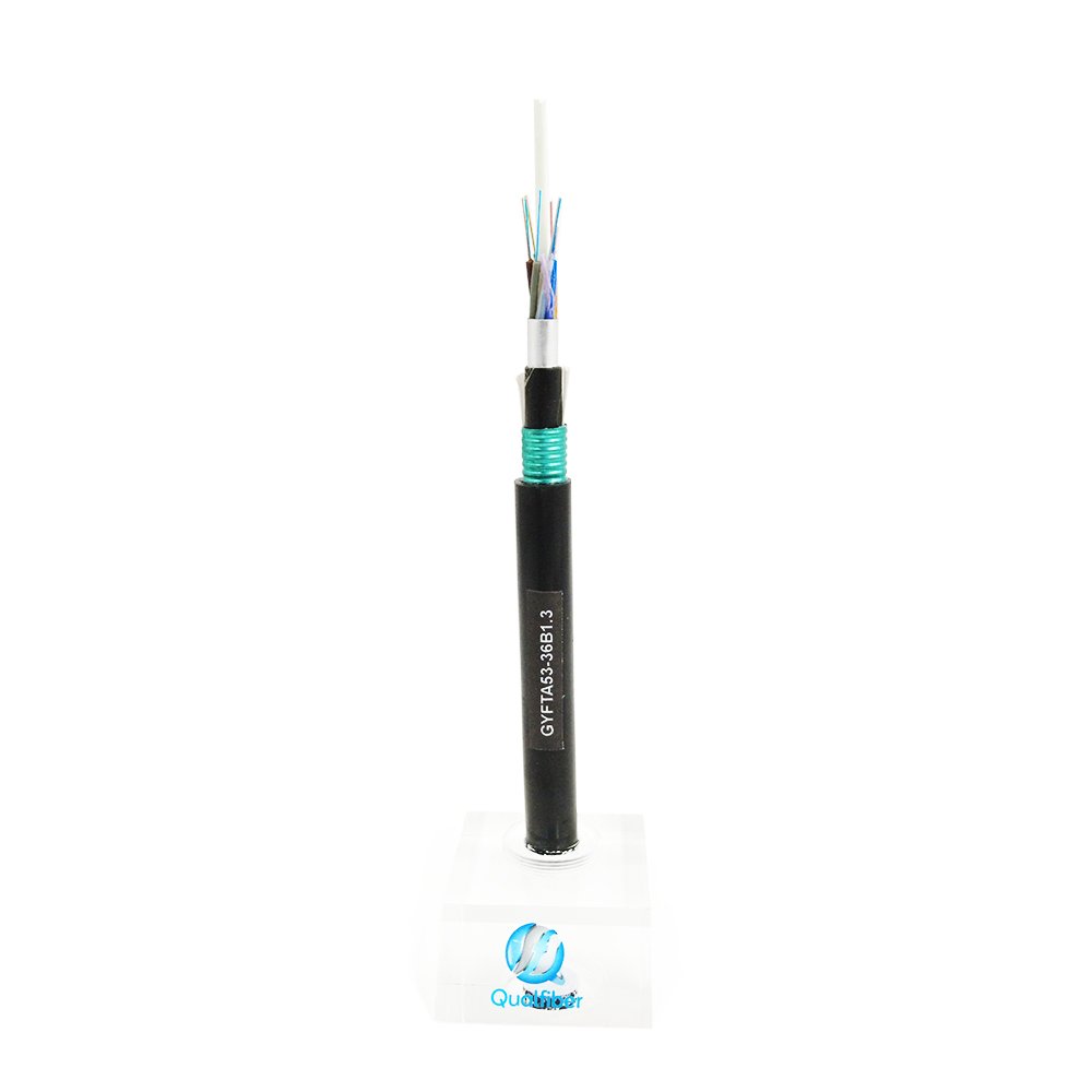
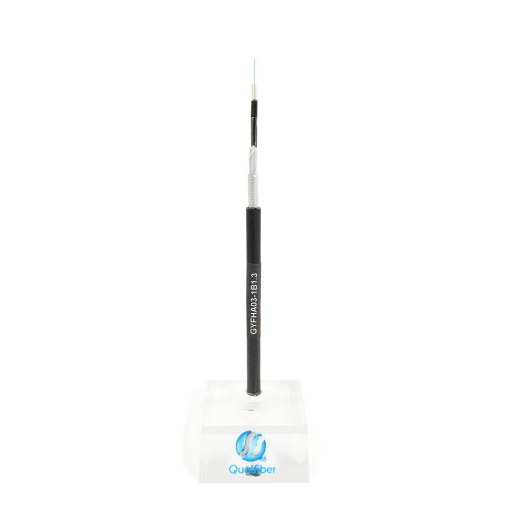
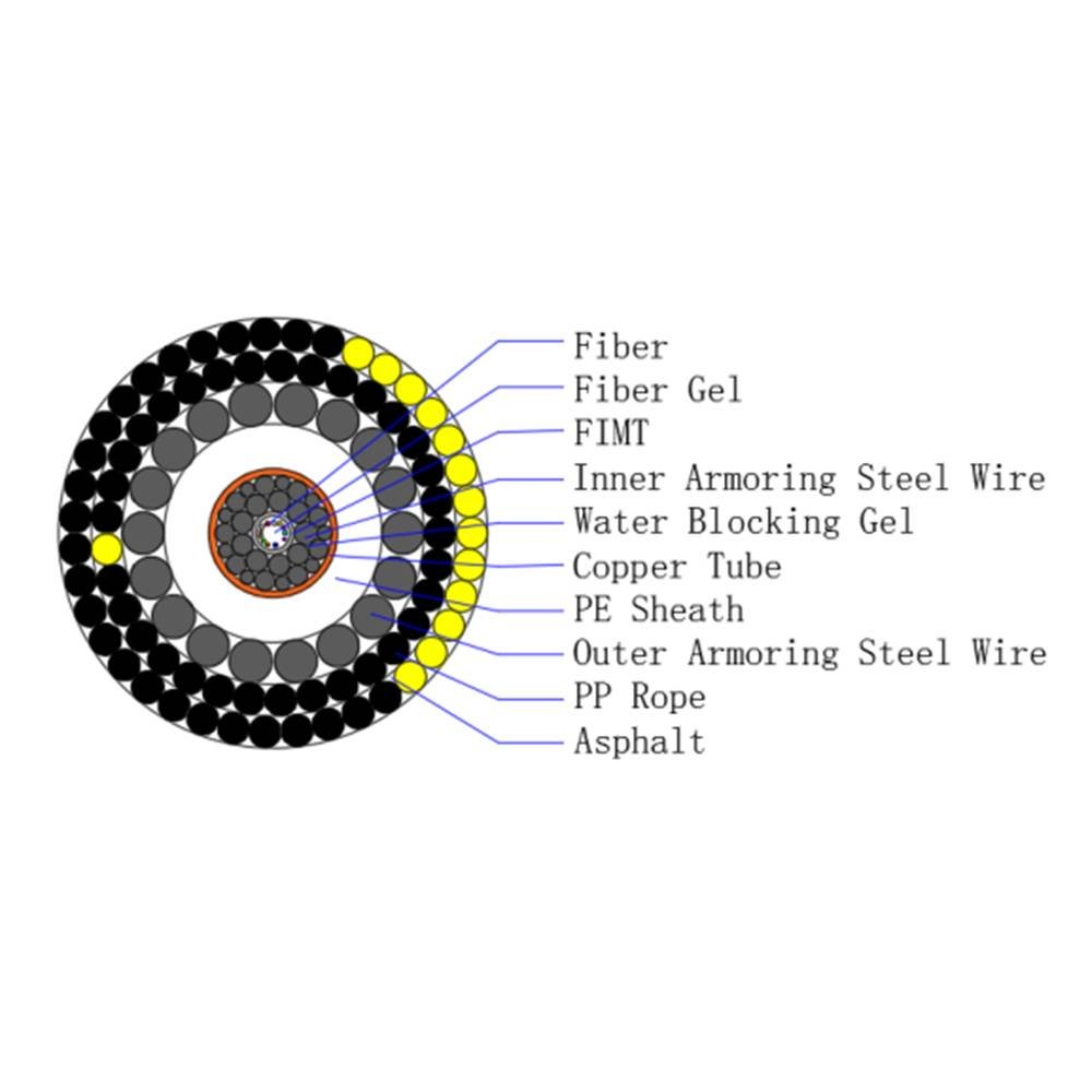
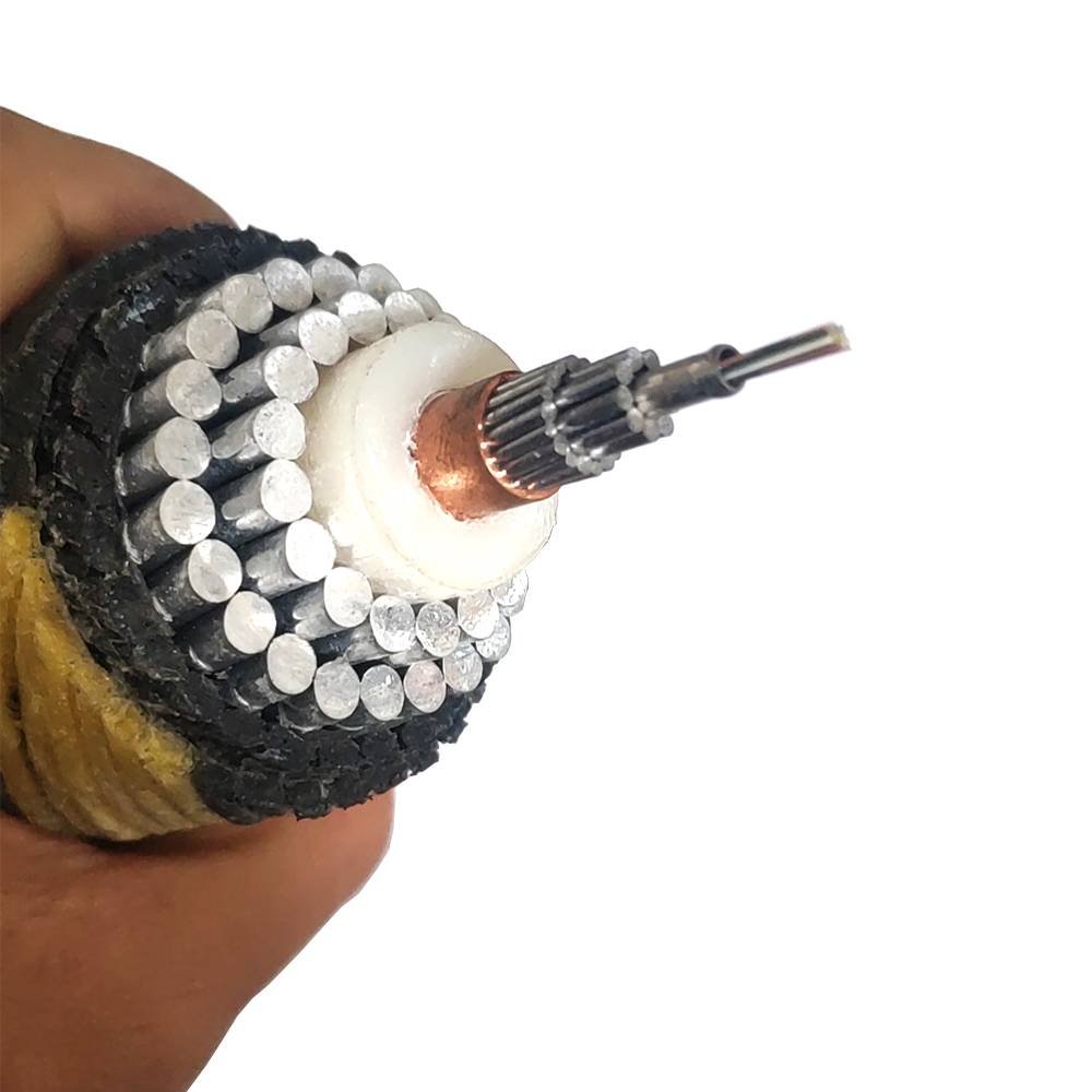
The basic structure of the submarine optical cable is: polyethylene layer, polyester resin or asphalt layer, steel strand layer, aluminum waterproof layer, polycarbonate layer, copper or aluminum tube, paraffin, alkane layer, optical fiber bundle, etc.
The submarine optical cable system is mainly used to connect optical cables and the Internet. It is divided into two parts: onshore equipment and underwater equipment. The onshore equipment packs and transmits communication services such as voice, image, and data.
Color:
Cable Design
| Item | Physical Characteristics | Unit | Nominal Value |
| Structure& Parameter | Fiber | No. | 24/48/95/144/288 |
| FIMTO.D. | mm | 02.7 | |
| O.D. | mm | 13.6 | |
| Cable O.D. | mm | 031.7 | |
| Weight in air, approximately. | kg/m | 02.7 | |
| Weight in seawater, approximately. | kg/m | 01.9 | |
| Item | Physical Characteristics | Unit | Nominal Value |
| Nominal | Maximum Deployment Ocean Depth | m | 600 |
Specification
| Hydrostatic pressure | MPa | 6 |
| Minimum Breaking Load,(UTS) | kN | 340 |
| Nominal Transient Tensile Load, (NTTS) | kN | 240 |
| Nominal Operating Tensile Load, (NOTS) | kN | 160 |
| Nominal Permanent Tensile Load, NPTS | kN | 120 |
| Minimum Bending Radius.(vNPTS) | m | 1.0 |
| Minimum Bending Radius.(>NPTS) | m | 1.5 |
| Operating Temperature Range | °C | -10~+40 |
| Handling Temperature Range | °C | -15~+45 |
| Storage Temperature Range | °C | -30-+60 |
| Operating Voltage | kV | 0.5 |
| DC withstand Voltage | - | 15kV,5min |
| Crush (IEC-794-1-E3) | kN | 40 |
| Impact (IEG794-1-E4) | J | 300 |
| Cable Resistance DC | Q/km | < 2.0 |
| Insulation resistance, conductor-water/ armoring | GQ.km | >10 |
| Cladding Diameter | μm | 125 | 1.0 |
| Cladding-Core Concentricity Error | μm | ≤1 | - |
| Cladding Non-circularity | % | ≤2 | - |
| Coating Diameter (uncolored) | μm | 245 | 10 |
| Coating-Cladding Concentricity Error | μm | ≤12 | - |
| Mode Field Diameter, MFD @ 1310 nm | μm | 9.2 | 0.4 |
| Attenuation @ 1310 nm | dB/km | ≤0.36 | - |
| Attenuation @ 1550 nm | dB/km | ≤0.22 | - |
| Zero Dispersion Wavelength | nm | 1300-1324 | - |
| Zero Dispersion Slope | ps/nm2 •km | ≤0.092 | - |
| Chromatic Dispersion @ 1310 nm | ps/nm • km | ≤3.5 | - |
| Chromatic Dispersion @ 1550 nm | ps/nm • km | ≤18 | - |
| Polarization Mode Dispersion, PMD | ps/vlcm | ≤ 0.2 | - |
| Cable Cut-off Wavelength | nm | ≤1260 | - |
| Proof Test Level | kpsi | >100 |
References
| Doc ID | Document Title |
| ISO 9001 | Quality Management Systems – Requirements |
| ISO 14001 | Environmental management systems |
| ITU-T G.652 | Characteristics of a single-mode optical fiber and cable |
| ITU-T G.654 | Characteristics of a cut-off shifted single-mode optical fiber and cable |
| IEC 60793-1 | Optical fiber Part 1: Generic specifications |
| IEC 60793-2 | Optical fiber Part 2: Product specifications |
| IEC 60794-1-2 | Generic specification-Basic optical cable test procedures |
| ITU-T G.976 | Test methods applicable to optical fiber submarine cable systems |
Write your message here and send it to us